MRF6S18060NR1 MRF6S18060NBR1
7
RF Device Data
Freescale Semiconductor
TYPICAL CHARACTERISTICS
Figure 13. MTTF Factor versus Junction Temperature
This above graph displays calculated MTTF in hours when the device
is operated at VDD
= 28 Vdc, P
out
= 60 W CW, and
ηD
= 50%.
MTTF calculator available at http://www.freescale.com/rf. Select
Software & Tools/Development Tools/Calculators to access MTTF
calculators by product.
250
108
90
106
105
104
110 130 150 170 190
MTTF (HOURS)
210 230
107
GSM TEST SIGNAL
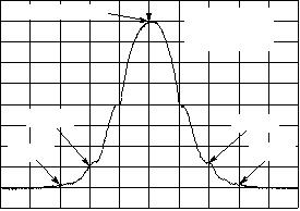
Figure 14. EDGE Spectrum
?10
?20
?30
?40
?50
?60
?70
?80
?90
?100
200 kHz Span 2 MHz
Center 1.96 GHz
?110
400 kHz
600 kHz
400 kHz
600 kHz
(dB)
Reference Power
VBW = 30 kHz
Sweep Time = 70 ms
RBW = 30 kHz


发布紧急采购,3分钟左右您将得到回复。
相关PDF资料
MRF6S18100NR1
MOSFET RF N-CH 28V 100W TO2704
MRF6S18140HSR5
MOSFET RF N-CH 28V ESD NI880S
MRF6S19060GNR1
MOSFET RF N-CH 28V TO-270-2 GW
MRF6S19100GNR1
MOSFET RF N-CH 28V TO-270-2 GW
MRF6S19100HSR5
MOSFET RF N-CHAN 28V 22W NI-780S
MRF6S19120HSR5
MOSFET RF N-CHAN 28V 19W NI-780S
MRF6S19140HSR5
MOSFET RF N-CHAN 28V 29W NI-880S
MRF6S19200HSR5
MOSFET RF N-CH 56W 28V NI780S
相关代理商/技术参数
MRF6S18060NR1
功能描述:射频MOSFET电源晶体管 1880MHZ 60W RoHS:否 制造商:Freescale Semiconductor 配置:Single 晶体管极性: 频率:1800 MHz to 2000 MHz 增益:27 dB 输出功率:100 W 汲极/源极击穿电压: 漏极连续电流: 闸/源击穿电压: 最大工作温度: 封装 / 箱体:NI-780-4 封装:Tray
MRF6S18060NR1_08
制造商:FREESCALE 制造商全称:Freescale Semiconductor, Inc 功能描述:RF Power Field Effect Transistors N-Channel Enhancement-Mode Lateral MOSFETs
MRF6S18100NBR1
功能描述:射频MOSFET电源晶体管 1990MHZ 28V RoHS:否 制造商:Freescale Semiconductor 配置:Single 晶体管极性: 频率:1800 MHz to 2000 MHz 增益:27 dB 输出功率:100 W 汲极/源极击穿电压: 漏极连续电流: 闸/源击穿电压: 最大工作温度: 封装 / 箱体:NI-780-4 封装:Tray
MRF6S18100NR1
功能描述:射频MOSFET电源晶体管 1990MHZ 28V RoHS:否 制造商:Freescale Semiconductor 配置:Single 晶体管极性: 频率:1800 MHz to 2000 MHz 增益:27 dB 输出功率:100 W 汲极/源极击穿电压: 漏极连续电流: 闸/源击穿电压: 最大工作温度: 封装 / 箱体:NI-780-4 封装:Tray
MRF6S18100NR1_08
制造商:FREESCALE 制造商全称:Freescale Semiconductor, Inc 功能描述:RF Power Field Effect Transistors N-Channel Enhancement-Mode Lateral MOSFETs
MRF6S18140HR3
功能描述:射频MOSFET电源晶体管 1.8GHZ 28V 29W RoHS:否 制造商:Freescale Semiconductor 配置:Single 晶体管极性: 频率:1800 MHz to 2000 MHz 增益:27 dB 输出功率:100 W 汲极/源极击穿电压: 漏极连续电流: 闸/源击穿电压: 最大工作温度: 封装 / 箱体:NI-780-4 封装:Tray
MRF6S18140HR3_09
制造商:FREESCALE 制造商全称:Freescale Semiconductor, Inc 功能描述:RF Power Field Effect Transistors N-Channel Enhancement-Mode Lateral MOSFETs
MRF6S18140HR5
功能描述:射频MOSFET电源晶体管 1.8GHZ 28V 29W RoHS:否 制造商:Freescale Semiconductor 配置:Single 晶体管极性: 频率:1800 MHz to 2000 MHz 增益:27 dB 输出功率:100 W 汲极/源极击穿电压: 漏极连续电流: 闸/源击穿电压: 最大工作温度: 封装 / 箱体:NI-780-4 封装:Tray
